 Placing panel connectors
|
Tool |
Workspace: Tool set |
|
Panel Connector
|
Design Suite and Spotlight: ConnectCAD Layout ConnectCAD: Layout |
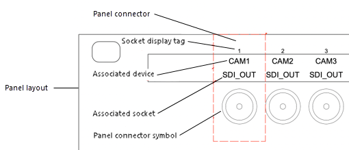
The panel connector displays a connector symbol and its label, to represent the schematic device and socket that the connector is linked to. The Panel Connector tool adds panel connectors to panel layouts (see Creating connector panel layouts).

|
Mode |
Description |
|
Single Click
|
Places a panel connector at the click location |
|
Linear Array
|
Places an array of panel connectors along the drawn line at the Spacing distance specified |
|
Grid Array
|
Places the panel connectors in a grid array at the Spacing distance specified |
|
Link-to Socket |
Select a schematic socket to link to the panel connector. The panel connector acquires the socket's data. Socket names from all panels matching the device type are available; the devices that have a panel of that style are listed first (see Creating panel layouts from schematic devices). |
|
Display Tag |
Enter the tag name (normally, this is the linked socket number) for display in the panel layout |
|
Connector |
Opens the Resource Selector to select a connector resource for placement |
|
Spacing |
Specifies the horizontal distance between the panel connectors in array modes |
To add panel connectors to a panel layout:
Double-click on a panel layout to open it in object editing mode (see De objectbewerkmodus). Both styled and unstyled panel layouts can be edited.
If the panel layout is not open in object editing mode, the layout is selected when you place the panel connectors (see step 4). To edit the panel connector parameters, open the layout in object editing mode.
Click the tool, and select the placement mode.
From the Tool bar, select the Link-to Socket name, enter the Display Tag, select a Connector symbol from the Resource Selector, and, if needed, specify the Spacing between the panel connectors in an array.
Click in the panel layout to place the panel connectors. The placement method depends on the selected mode.
In Single Click mode, click once to place the panel connector.

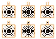
In one of the array modes, click once to start the array; move the cursor to set the direction of the array. The preview indicates the spacing and placement of the objects; the floating Data bar shows the Count. Click to place the array. The panel connectors are automatically numbered sequentially.

The panel connector parameters can be edited from the Object Info palette.
Click to show/hide the parameters.Click to show/hide the parameters.
|
Parameter |
Description |
|
General |
|
|
Linked to Socket |
Select a socket linked to the panel connector. Socket names from all panels matching the device type are available; the devices that have a panel of that style are listed first (see Creating panel layouts from schematic devices). Linking to a socket populates the Display Tag, Connected Device, and Connected Socket. Select Other to open the Other Socket Name dialog box and enter a socket name. |
|
Display Tag |
Enter the tag name (normally, this is the linked socket number) for display in the panel layout |
|
Symbol |
Displays the connector panel symbol. Open the Resource Selector to select a different connector resource for placement. |
|
Connected-to Labels |
|
|
Connected Device |
Displays the device that the panel connector is linked to |
|
Connected Socket |
Displays the socket that the panel connector is linked to |
|
Display |
|
|
Text Vertical Offset |
Specifies the space between the panel connector symbol and the text on the display tag, connected device, and/or connected socket |
|
Show display tag |
Displays the display tag above the panel connector symbol |
|
Show connected device |
Displays the connected device name above the panel connector symbol |
|
Show connected socket |
Displays the connected socket name above the panel connector symbol |
Exit object editing mode to return to the panel layout.
![]()
Heb je niet gevonden wat je zocht? Stel je vraag aan Dex, onze virtuele assistent.


