 Shaft segment properties
To add, delete, or modify component segments to construct the desired shaft object:
Select a shaft in the drawing file and click the Configuration button from the Object Info palette.
While the currently selected segment is highlighted, specify the shaft segment parameters on each tab to define the shaft. Click the Update button to dynamically change the preview when changes are made.
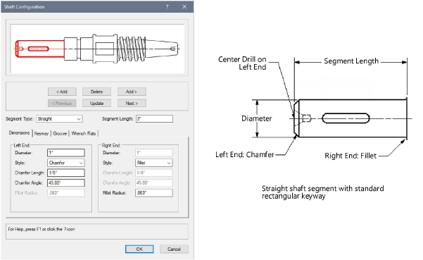
Click the Dimensions tab to specify the configuration of the shaft segment.
Click to show/hide the parameters.Click to show/hide the parameters.
|
Parameter |
Description |
|
< Add/Add > |
Click < Add to add a shaft segment to the left of the current segment or click Add > to add a shaft segment to the right of the current segment |
|
Delete |
Deletes the current shaft segment |
|
< Previous/Next > |
Click Previous to select the shaft segment to the left of the current segment or click Next to select the shaft segment to the right of the current segment |
|
Update |
Updates the preview image for the current segment |
|
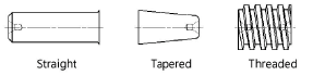
Segment Type |
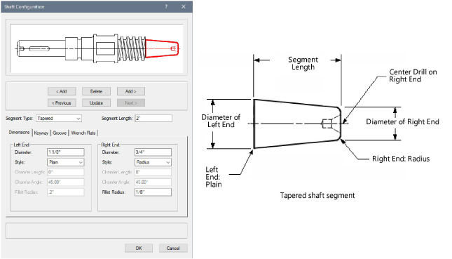
Select a straight, tapered, or threaded shaft segment type
|
|
Segment Length |
Specify the shaft segment length |
|
Diameter |
For straight or tapered segments, enter the diameter of the ends |
|
Style |
For straight or tapered segments, select the end style |
|
Chamfer Length |
For straight or tapered segments, specify the length for chamfer/flare ends styles |
|
Chamfer Angle |
For straight or tapered segments, specify the angle value for chamfer/flare ends styles |
|
Fillet Radius |
For straight or tapered segments, specify the radius value for fillet/radius end styles |
|
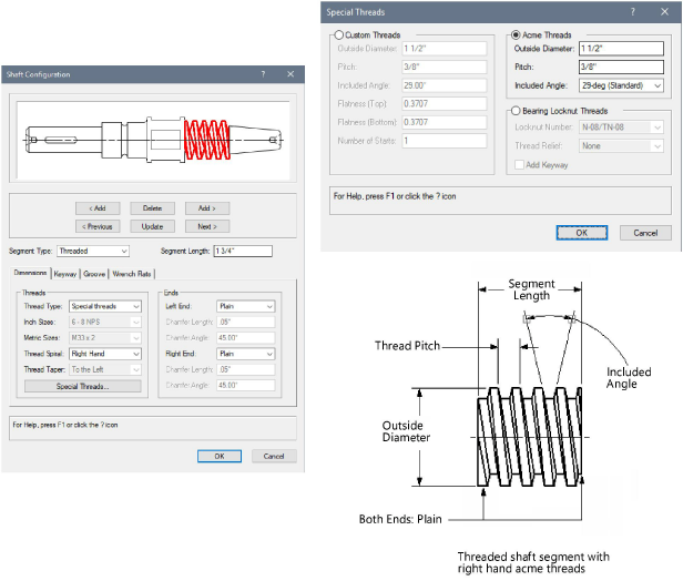
Thread Type |
For threaded segments, select the standard inch or metric thread series, or select special threads to specify custom, Acme, or bearing locknut thread parameters; the selection in this field enables the associated thread size parameter or Special Threads button |
|
Inch Sizes |
For standard inch series, select the thread size and threads per inch |
|
Metric Sizes |
For standard metric series, select the thread size and pitch |
|
Thread Spiral |
For threaded segments, select whether to draw left hand or right hand threads |
|
Thread Taper |
For tapered pipe threads, select whether the taper points to the left or right |
|
For threaded segments, click Special Threads to specify custom, acme, or bearing locknut thread parameters. For custom threads, enter the outside diameter of threads, the thread pitch, the included angle of the threads, the flatness at both the top (at the outside diameter) and bottom (at the root diameter) of the threads, and the number of starts. For Acme threads, enter the outside diameter of threads, the thread pitch, and select the included angle of the threads. For bearing locknut threads, select the bearing locknut number, the thread relief position (if any), and add a keyway, if desired. |
|
|
Left End/Right End |
For threaded segments, select plain or chamfered for the left and right ends |
|
Chamfer Length |
For threaded segments, specify the length for chamfer end styles |
|
Chamfer Angle |
For threaded segments, specify the angle value for chamfer end styles |
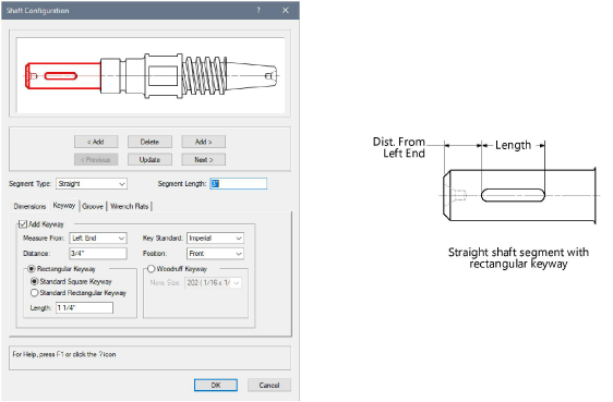
Click the Keyway tab to specify the configuration of the shaft segment keyway (straight Segment Type only).
Click to show/hide the parameters.Click to show/hide the parameters.
|
Parameter |
Description |
|
Add Keyway |
For straight segments, select Add Keyway to add a keyway to the current segment |
|
Measure From |
Select to measure the position of the keyway from the left or right end |
|
Distance |
Enter the distance from the end of the segment to the keyway |
|
Key Standard |
Select to insert either an imperial or metric keyway |
|
Position |
Select to position the keyway in the front, top, bottom, or back of the segment |
|
Parallel Keyway/Rectangular Keyway |
Select to add a rectangular or parallel keyway; specify either a standard square or rectangular keyway, and enter the keyway length |
|
Woodruff Keyway |
Adds a woodruff keyway; select the nominal size |
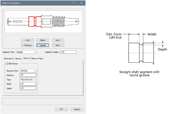
Click the Groove tab to specify the configuration of the shaft segment groove (straight Segment Type only).
Click to show/hide the parameters.Click to show/hide the parameters.
|
Parameter |
Description |
|
Add Groove |
For straight segments, select Add Groove to add a groove to the current segment |
|
Measure From |
Select to measure the position of the groove from the left or right end |
|
Distance |
Enter the distance from the end of the segment to the groove |
|
Type |
Select to add a round, rectangular, or V-groove |
|
Width |
Enter the groove width |
|
Depth |
Enter the groove depth |
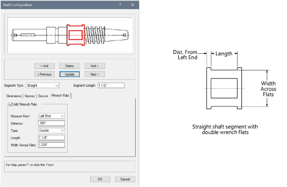
Click the Wrench Flats tab to specify the configuration of the shaft segment wrench flats (straight Segment Type only).
Click to show/hide the parameters.Click to show/hide the parameters.
|
Parameter |
Description |
|
Add Wrench Flats |
For straight segments, select Add Wrench Flats to add wrench flats to the current segment |
|
Measure From |
Select to measure the position of the wrench flats from the left or right end |
|
Distance |
Enter the distance from the end of the segment to the groove |
|
Type |
Select to add single or double wrench flats |
|
Length |
Enter the wrench flats length |
|
Width Across Flats |
Enter the width across flats of the wrench flats |
To edit parameters, click Configuration from the Object Info palette, double-click the shaft, or select Edit from the context menu to open the Shaft dialog box. The following additional parameters can be modified directly from the Object info palette.
Click to show/hide the parameters.Click to show/hide the parameters.
|
Parameter |
Description |
|
Configuration |
Click Configuration to open the Shaft Configuration dialog box |
|
Add Center Drill |
Draws the shaft with a center drill. Select either a plain or bell configuration for the center drill, select the size, and whether a center drill is drawn on the left, right, or both ends of the shaft. |
|
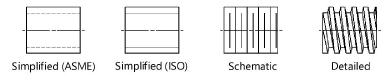
Show Threads As |
Select how to draw the 2D threaded shaft threads
|
|
Show Center Line |
Draws the 2D shaft with center line(s) |
|
Show Threads |
Draws the 3D shaft with threads |
|
Create Solid |
Creates a generic solid from the individual 3D segments. For large, complex shafts, this will greatly reduce file size. Deselect this option when editing the shaft to speed the editing process. |

Heb je niet gevonden wat je zocht? Stel je vraag aan Dex, onze virtuele assistent.