 Gears
Gears
Spur gears
|
Mode |
Tool |
Tool set |
|
Modes for Narzędzie Wstaw symbol |
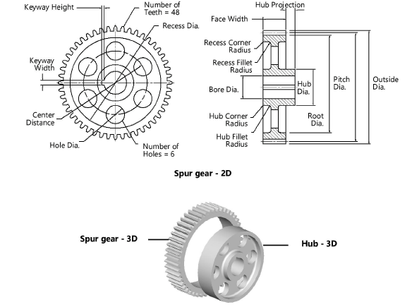
Spur Gear
|
Machine Components |


Multiple spur gear, spur gear rack, and hub tools share the same position on the tool set. Click and hold the mouse on the visible tool to open the Narzędzia ukryte list and select the desired tool.
To insert a spur gear:
Click the tool and mode.
Kliknij, aby pokazać/ukryć parametry. place the object, and click again to set the rotation. The first time you use the tool in a file, a properties dialog box opens. Set the default parameters. The parameters can be edited later from the Object Info palette.
If you inserted a 3D spur gear, click the Hub - 3D tool from the Machine Components tool set to insert a 3D hub. Place the hub in the drawing and set the default properties, if prompted.
Kliknij, aby pokazać/ukryć parametry.Kliknij, aby pokazać/ukryć parametry.
|
Parameter |
Description |
|
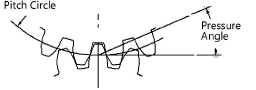
Pitch Diameter |
Specify the pitch diameter |
|
Number of Teeth |
Enter the number of teeth |
|
Pressure Angle |
Enter the pressure angle
|
|
Diametrical Pitch (Ref.) |
Displays the diametrical pitch (for reference only) |
|
Module (mm) (Ref.) |
Displays the module (for reference only) |
|
Outside Dia. (Ref.) |
Displays the outside diameter (for reference only) |
|
Root Dia. (Ref.) |
Displays the root diameter (for reference only) |
|
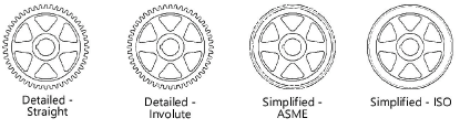
Tooth Profile |
Select the type of tooth profile
|
|
Face Width |
Enter the width of the gear face |
|
Helix Angle (3D only) |
Indicate the 3D spur gear helix angle |
|
Hole Diameter (3D only) |
Indicate the hole diameter for the 3D spur gear; when including a hub 3D object in the drawing, adjust the spur gear hole diameter and hub outside diameter to fit together |
|
Draw Recess (2D only) |
To draw a recessed web, select Draw Recess and specify the 2D parameters |
|
Web Thickness |
Enter the web thickness |
|
Recess Diameter |
Enter the recess diameter |
|
Recess Corner Radius |
Enter the recess corner radius |
|
Recess Fillet Radius |
Enter the recess fillet radius |
|
Draw Hub (2D only) |
Draws a hub |
|
Hub Diameter |
Enter the hub diameter |
|
Hub Projection (Left/Right) |
Specify the amount of projection for the hub on both the left and the right; a negative value indicates that the hub face is recessed |
|
Hub Corner Radius |
Enter the hub corner radius |
|
Hub Fillet Radius |
Enter the hub fillet radius |
|
Draw Bore (2D only) |
Draws a bore |
|
Bore Diameter |
Enter the bore diameter |
|
Keyway |
If a keyway is present, select the square, rectangular, or custom size; the square and rectangular selections apply the ASME-recommended size based on the bore diameter |
|
Width/Height |
For custom keyway sizes, enter the width and height values of the keyway |
|
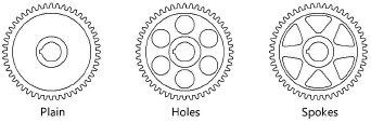
Web Configuration (2D only) |
Select the web configuration and then specify the 2D parameters, if any. When Holes is selected, hole size can be specified as a percentage or diameter value.
|
|
Number |
Indicate the number of holes or spokes for the gear (does not apply to Plain web configurations) |
|
Size (10–100%) |
For Holes (Percent) and Spokes web configurations, enter the percentage of the recess opening occupied by the holes or spokes |
|
Center Distance |
When Holes is selected for the web configuration, specify the distance between the hole centers |
|
Hole Diameter |
When Holes is selected for the web configuration, indicate the size of the holes |
|
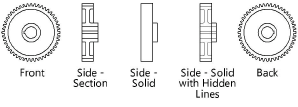
View (2D only) |
Select the 2D view
|
|
Show Center Lines (2D only) |
Draws the 2D gear with center lines |

Potrzebujesz więcej informacji? Poproś o pomoc naszego wirtualnego asystenta Dexa! ![]()