 Inserting a point load
|
Mode |
Tool |
Tool set |
|
Point Load
|
Rigging Load
|
Rigging/Braceworks |


To insert a point load:
Click the tool and mode.
Do one of the following:
To use a saved set of load properties, click Load Settings on the Tool bar and select the load set.
If not using a saved load set, specify the Load Category, enter the point load’s total Weight, and select the orientation of the text label from the Tool bar.
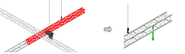
Move the mouse to the rigging object where the point load is to be hung, near the center line.
Valid rigging objects are highlighted.
Click to place the point load at that location. The point load is placed at the centerline of the rigging object.
In Top/Plan view, the point load label displays at the orientation selected from the Tool bar at placement. It can be moved by clicking and dragging the label control point. The legend displays over the point load.
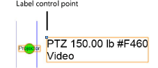
The parameters can be edited later from the Object Info palette.
Click to show/hide the parameters.Click to show/hide the parameters.
|
Parameter |
Description |
|
Text Style |
Select a text style from a library or the current file (does not apply to the legend text). To use the style defined for the object's class, select <Class Test Style>. To format the text using options on the Text menu, select <Un-Styled>. See Tekststijlen gebruiken and Tekst opmaken. |
|
Legend Entry |
Enter text for an optional unique object label |
|
Load Category |
Specifies the load category, which is important for calculations (Braceworks required) |
|
Show Name |
Displays the Load Name in the label |
|
Show Load Category |
Displays the Load Category in the label |
|
Show Symbol |
Display the selected symbol instead of default geometry |
|
Symbol |
Displays the symbol used to represent the point load, and opens the Resource Selector. The generic point load representation can be switched to use a symbol instead. For example, a chandelier symbol could be used instead. From the Resource Selector, double-click a different resource to apply it. |
|
Opens the Classes dialog box, to specify class naming for the point load and label. This allows the point load or label to be set to visible, grayed, or invisible. Use the standard class, select a class from the list of classes present in the drawing, or create a new class. Select <Object Class> to place the point load element in the same class as the object. Use Standard Classes: Sets the class names for the point load and label to the standard Point load elements: For the point load and label, specifies the class name standard; the class names shown here are applied to the elements |
|
|
Select Similar Objects |
|
|
Objects of same name |
Selects point load objects with the same Load Name parameter |
|
Objects of same load category |
Selects point load objects with the same Load Category parameter |
|
Objects of same weight |
Selects point load objects with the same Total Weight parameter |
|
Load information |
Load information is used for Braceworks calculations and reports (Braceworks required) |
|
Include in calculations (Braceworks required) |
Includes the point load in Braceworks calculations; deselect to exclude the point load from participating in structural calculations |
|
Load Group Name |
Displays the selected load category |
|
Load ID |
Enter a unique ID for the load for informational use in reports |
|
Load Name |
Identifies the object in load calculations |
|
Total Weight |
Enter the total weight of the object |
|
Position |
Displays the name of the associated rigging object, if the load is attached. Optionally, attach this object to a rigging object, or change the rigging object association, by entering the Position Name of the rigging object. Delete the name to break the association. For other methods to attach loads, see Making the attachment. |
Adding a point load automatically
|
Command |
Workspace: Path |
|
Add Point Loads at Selection |
Design Suite: Entertainment > Rigging/Braceworks Spotlight: Spotlight > Rigging/Braceworks |
If the exact placement of the point load is not critical, a point load can be added automatically to the rigging objects in the drawing. In addition, the command can easily add a point load to any selected object or objects, including symbols. For example, you can select several symbols, and the command adds a load to the insertion point of each one.
To add a point load automatically:
Select the rigging object (or other object or objects) where the point load will be placed. When more than one object is selected, a point load is placed on each one.
Select the system to easily select more than one rigging object, and automatically add the same load to each.
Select the command.
The Load Settings dialog box opens, for Creating and selecting load sets. Select a load set, or enter load parameters and select the <Active Settings> set.
A point load is placed on each object, at its start point or insertion point.
Heb je niet gevonden wat je zocht? Stel je vraag aan Dex, onze virtuele assistent.