 Creating a riser sheet
|
Command |
Workspace: Path |
|
Create Riser Sheet |
Design Suite: Entertainment > ConnectCAD Documentation Spotlight: Spotlight > ConnectCAD Documentation ConnectCAD: ConnectCAD > Documentation |
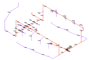
A riser diagram shows the electrician what ducts (cable containers) to install and where to install them. It can be considered a map of the cable ducts, annotated with the duct size and cable information that has been provided by the designer. Riser diagrams are created automatically as viewports on a sheet layer; see Zichtvensters op presentatielagen creëren.
To create a riser sheet:
Adjust the view to give a clear picture of the cable paths.
Select the command.
The Create Riser Sheet dialog box opens. Specify the destination layer for the riser sheet, its view, and the annotation method for the cable paths.
Click to show/hide the parameters.Click to show/hide the parameters.
|
Parameter |
Description |
|
Sheet Layer (Destination) |
Select the sheet layer where the riser sheet will be created, or select New Sheet Layer to create a sheet layer |
|
Viewport Name |
A viewport name is provided automatically; edit the name if needed |
|
Viewport View |
Select the view for the riser sheet. By default, the current view is selected so it matches the initial view you adjusted. |
|
Cable Path Annotation |
Select whether to automatically or manually annotate the cable path objects with their container size or other information. You might want to auto-annotate a main view, and manually clarify details in other views. |
|
Auto-annotate |
Automatically places a data tag on each cable path object; data tags can be edited later from the viewport's annotation layer |
|
Annotate manually |
Automatically opens the viewport's annotation layer with the Data Tag tool selected, ready for cable path annotation |
|
Do not annotate |
Does not annotate the cable paths |
The riser diagram viewport is created and placed on the sheet layer.
If you are manually annotating the cable path objects, the Data Tag tool is selected and the viewport's annotation layer opens, ready for tagging.
After creation, the data tags can be edited from the viewport's annotation layer. See Aantekeningen plaatsen in een zichtvenster and Gegevenslabels bewerken.
The container size information displayed in the data tag comes from the Path Info record that is included within the CC Cable Container record format (which is attached to cable path objects). Edit the list by editing the record format; see Een recordhulpbron bewerken.
Heb je niet gevonden wat je zocht? Stel je vraag aan Dex, onze virtuele assistent.